
 Zhejiang wanlai Intelligent electric co., ltd.


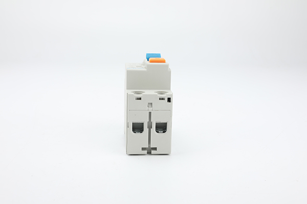
JCRD2-125 RCD residual current circuit breaker , 2 Pole Type AC or Type A
JCR2-125 RCD is a sensitive current breaker designed to protect the user and their property from electric shock and potential fires by breaking the current as is passes through your consumer unit/ distribution box in the event of a detected imbalance or disruption to current path.
Introduction:
A residual-current device (RCD), residual-current circuit breaker (RCCB) is an electrical safety device that quickly breaks an electrical circuit with leakage current to ground. It is to protect equipment and to reduce the risk of serious harm from an ongoing electric shock. Injury may still occur in some cases, for example if a human receives a brief shock before the electrical circuit is isolated, falls after receiving a shock, or if the person touches both conductors at the same time.
JCR2-125 are designed to disconnect the circuit if there is a leakage current.
JCR2-125 Residual current devices (RCDs) prevent you from receiving fatal electric shocks. RCD protection is life-saving and protects against fires. If you touch a bare wire or other live components of a consumer unit, it will keep the end user from being harmed. If an installer cuts through a cable, residual current devices will switch off the power flowing to the earth. The RCD would be used as the incoming device which feeds the electrical supply to the circuit breakers. In the event of an electrical in-balance, the RCD trips out and disconnects the supply to the circuit breakers.
A residual current device or better known as an RCD is a key safety device in the electrical world. An RCD is used primarily to protect a human being from a hazardous electrical shock. If there is a defect with an appliance in the household, the RCD reacts because of the power surge and disconnects the electric current. The RCD is fundamentally designed to respond quickly. The residual current device oversees the electric current and the instant of any abnormal activity the device rapidly reacts.
RCD's exist in various different forms and react differently depending on the presence of DC components or different frequencies. The level of safety they provide for live currents is greater than an ordinary fuse or circuit breaker. The following RCD's are available with the respective symbols and the designer or installer is required to select the appropriate device for the specific application.
Type S (Time-delayed)
A Type S RCD is a sinusoidal residual current device incorporating a time delay. It can be installed upstream from a Type AC RCD to provide selectivity. A time-delayed RCD cannot be used for additional protection because it will not operate within the required time of 40 mS
Type AC
Type AC RCDs (General Type), which are most commonly installed in dwellings, are designed to be used for alternating sinusoidal residual current to protect equipment which is resistive, capacitive or inductive and without any electronic components.
General Type RCDs do not have a time delay and operate instantaneously on detection of imbalance.
Type A
Type A RCDs are used for alternating sinusoidal residual current and for residual pulsating direct current up to 6 mA..

Product Description:

Main Features
● Electromagnetic type
● Earth leakage protection
● Breaking capacity up to 6kA
● Rated current up to 100A (available in 25A, 32A, 40A, 63A, 80A,100A)
● Tripping sensitivity: 30mA,100mA, 300mA
● Type A or Type AC are available
● Positive Status Indication Contact
● 35mm DIN rail mounting
● Installation flexibility with the choice of line connection either from top or bottom
● Complies with IEC 61008-1, EN61008-1
Tripping sensitivity
30mA – additional protection against direct contact
100mA – co-ordinated with the earth system according to the formula I△n<50/R, to provide protection against indirect contacts
300mA – protection against indirect contacts, as well as fire harzard
Technical Data
● Standard: IEC 61008-1, EN61008-1
● Type: Electromagnetic
● Type (wave form of the earth leakage sensed): A or AC are available
● Poles: 2 pole, 1P+N
● Rated current: 25A, 40A , 63A, 80A,100A
● Rated working voltage: 110V, 230V, 240V ~ (1P + N)
● Rated sensitivity I△n: 30mA, 100mA, 300mA
● Rated breaking capacity: 6kA
● Insulation voltage: 500V
● Rated frequency: 50/60Hz
● Rated impulse withstand voltage(1.2/50) : 6kV
● Pollution degree:2
● Mechanical life: 2,000 times
● Electrical life: 2000 times
● Protection degree: IP20
● Ambient temperature (with daily average ≤35℃):-5℃~+40℃
● Contact position indicator: Green=OFF, Red=ON
● Terminal connection type: Cable/Pin-type busbar
● Mounting: On DIN rail EN 60715 ( 35mm) by means of fast clip device
● Recommended torque: 2.5N.m
● Connection: From top or bottom are available
| Standard | IEC61008-1 , EN61008-1 | |
| Electrical features |
Rated current In (A) | 25, 40, 50, 63, 80, 100, 125 |
| Type | Electromagnetic | |
| Type (wave form of the earth leakage sensed) | AC, A, AC-G, A-G, AC-S and A-S are available | |
| Poles | 2 Pole | |
| Rated voltage Ue(V) | 230/240 | |
| Rated sensitivity I△n | 30mA,100mA,300mA are available | |
| Insulation voltage Ui (V) | 500 | |
| Rated frequency | 50/60Hz | |
| Rated breaking capacity | 6kA | |
| Rated impulse withstand voltage(1.2/50) Uimp (V) | 6000 | |
| Dielectric test voltage at ind. Freq. for 1 min | 2.5kV | |
| Pollution degree | 2 | |
| Mechanical features |
Electrical life | 2, 000 |
| Mechanical life | 2, 000 | |
| Contact position indicator | Yes | |
| Protection degree | IP20 | |
| Reference temperature for setting of thermal element(℃) | 30 | |
| Ambient temperature (with daily average ≤35℃) | -5...+40 | |
| Storage temperation (℃) | -25...+70 | |
| Installation | Terminal connection type | Cable/U-type busbar/Pin-type busbar |
| Terminal size top/bottom for cable | 25mm2 , 18-3/18-2 AWG | |
| Terminal size top/bottom for Busbar | 10/16mm2 ,18-8 /18-5AWG | |
| Tightening torque | 2.5 N*m / 22 In-Ibs. | |
| Mounting | On DIN rail EN 60715 (35mm) by means of fast clip device | |
| Connection | From top or bottom |
How do I test the different Types of RCD?
There are no additional requirements for the installer to check for correct operation whilst subjected to DC residual current. This testing is carried out during the manufacturing process and is called type testing, which is no different from the way we currently rely on circuit-breakers under fault conditions. Type A, B and F RCDs are tested in the same way as an AC RCD. Details of the test procedure and maximum disconnection times can be found in IET Guidance Note 3.
What if I discover a Type AC RCD whilst carrying out an electrical inspection during an electrical installation condition report?
If the inspector is concerned that residual DC current may affect the operation of Type AC RCDs, the client must be informed. The client should be informed of the potential dangers which may arise and an assessment of the amount of residual DC fault current should be made to determine if the RCD is suitable for continued use. Depending on the amount of residual DC fault current, an RCD which is blinded by residual DC fault current is likely not to operate which could be as dangerous as not having an RCD installed in the first place.
In-service reliability of RCDs
Many studies on the in-service reliability have been carried out on RCDs installed in a wide range of installations providing an insight into the effects that environmental conditions and external factors can have on the operation of an RCD.


